 home page
home page
The material point method (MPM) is a kind of the finite element method formulated in an arbitrary Lagrangian-Eulerian description of motion (ALE). Two kinds of spatial discretization are used in the method. The region occupied initially by the considered body is divided into a set of subregions. Each subregion is represented by one its point (called a material point); motion of all these points is traced with respect to an element mesh chosen independently of the material points. This mesh, called a computational mesh, should cover the virtual position of the analysed body (Fig. 1). The computational mesh can be chosen in an arbitrary way (it can remain constant for the entire computation process or be changed even step by step) which means that the main disadvantage of the standard finite element method related to the problem of mesh distortions is eliminated.
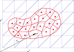 |
The material point method belongs to the group of so called meshless methods, in which motion of points (particles), not elements (subregions) are traced. The history of state variables is also traced for these points. The material point method was applied as a tool of analysis for problems of solid mechanics in the last decade. The method, known also as the particle-in-cell method, was successfully used earlier in fluid mechanics and other areas of physics like: astrophysics and plasma physics.
An application of MPM in analysis of granular flow in a silo is presented below. The method seems to be an efficient tool of analysis of other large strain engineering problems like: forming problems, landslide problem and motion of avalanches.
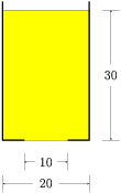
Gravitational flow of a granular material in an axisymmetric silo is considered. The cross-section of the silo is shown in Fig. 2, where dimensions are given in centimeters. The granular material is modelled as the elastic-plastic body with the Drucker-Prager yield condition and non-associated flow rule. The material data are as follows: Young modulus = 1 MPa, Poisson ratio = 0.3, mass density = 1500 kg/m3, the internal friction angle = 25o, the angle of friction between the flowing material and silo walls = 20o.
 |
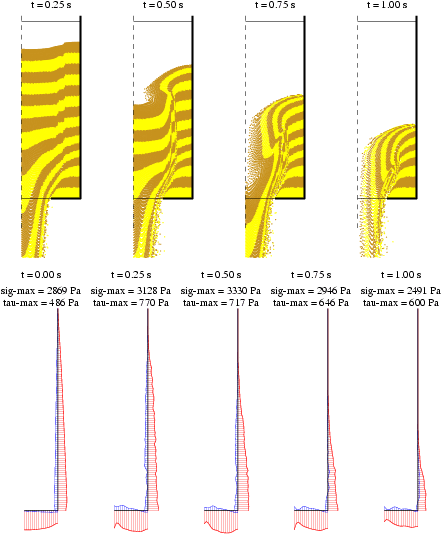
In the analysis, the computational mesh consisting of 9902 triangular elements with linear shape functions has been used; 31112 material points have been introduced. The obtained results are shown in Fig. 3 - the flow pattern and interactions between the flowing material and the silo walls are shown for some time instants. Normal and tangential tractions are depicted in red and blue colours, respectively. It can be seen that the direction of the tangential tractions along the vertical wall changes after developing the discharge process due to unloading of the material remaining in the silo corner.
 |
Animation for the above flow is available by choosing one option below:
The above computations have been made by the use of the computer program FENAP.
home page